


Hello. It's been a long time (as usual). Today, finally, there is something that I want to share with you. It started from that the company We had the opportunity to build a Proof of Concept (POC) that requires a microcontroller (MCU such as Arduino, Raspberry Pi) and I wanted a screen to operate the MCU that was a modern screen. Instead of a button or a screen that has only letters after finding it, it finds it with a screen called Nextion HMI Display.
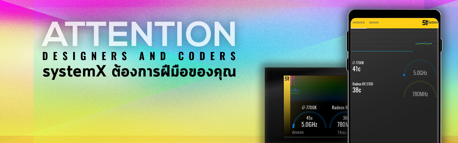
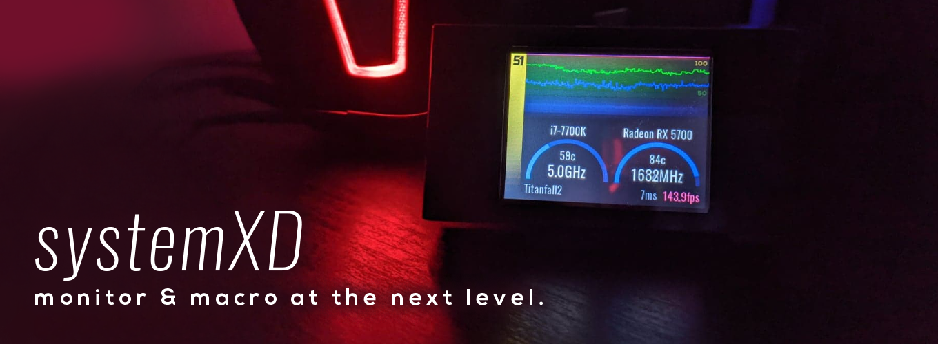
After doing the POC, I used the knowledge I gained, added our systemX program so that it could send values to Nextion, and designed a screen to run on Nextion, and came up with a screen like the one pictured above. and saw that it could be sold So I made it out as a Product called systemXD~ Anyone who wants a finished product Comes with base, frame and USB cable, you can contact us via chat in the bottom corner or inbox http://m.me/level51pc to order Compatible with all brands of machines just install systemX
We also made a skin system, systemX can download the skin and upload it to the screen itself. Without the Nextion Editor program, if anyone has the ability to create graphics and want to try it, read this post and follow it. We have a systemXD screen to give away to use for the first 5 people who submit skins to the system. For details , click here or click on the image below.
it's for this blog I'm going to introduce how to write programs into the Nextion screen, from designing the screen, writing the code, as well as connecting to other devices. complete and complete The example we're going to create today is to plug it into a computer and use our SystemX program as a temperature transmitter. The speed of our machine comes out which if done It can be applied to other MCUs, and of course, if it's a complete skin, it works with systemX as well.
provide program
To design a screen for Nextion, you will need the Nextion Editor program. You can download it from this web page. https://nextion.tech/nextion-editor/

Another program to use is our SystemX. because it will be a program that reads the values of Sensors in our machine and sends commands to the Nextion, downloadable from http://www.level51pc.com/systemx _
And finally, so that we can develop the screen without having to wait to upload it to the Nextion really messed up, is the COM Port emulator that loops in our own machine so that SystemX can send data to the Nextion Editor. I use the one that Com0Com is an Open Source program. You can download and install it from this link.
HTTPS://SOURCEFORGE.NET/PROJECTS/COM0COM/FILES/COM0COM/3.0.0.0/
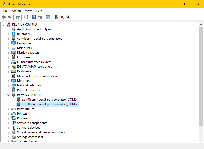
after installation In the machine will show up as two new COM Ports in pairs. that must be matched because the COM Port when it is opened with one program Another program will not work. If we want two programs to send data to each other through the COM Port, we must have a pair. For the two programs that SystemX has already made to support com0com. If it can't find the CH340 USB->TTL (as it says CH340 in its name), it will try to use the first com0com it finds.
Get to know Nextion Editor
The Nextion Editor program is a program called an IDE (Integrated Development Environment), meaning it has all the tools you need to use. integrated into one screen No need to open and open to type commands to be messy.
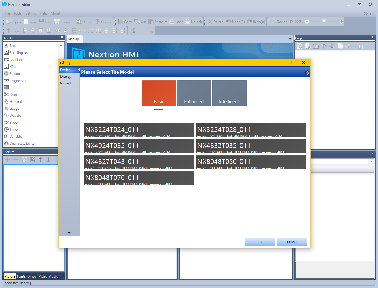
Once you've logged into the program, you can start by pressing New , and once you 've chosen where to save the file, you'll need to select the screen version as well. which can be flipped to look at the back What we use will be the model. NX3224T024_011 which is in the "Basic" group
The difference between Basic, Enhanced, Intelligent is in the ability of the MCU that comes with the screen. The Enhanced has more RAM than Flash (can put a lot of pictures) and can communicate with other devices via GPIO itself. too, which is beyond our needs and the highest Intelligent will be the one with the GPU capable of playing video. You can use an image with a clear background. can make control clear But it is much more expensive than other models and only has a screen size of 7/10 inches, which is much more than our needs.
The next step is to choose which style to display. We choose horizontal 90 is that the plug will be on the left hand side.
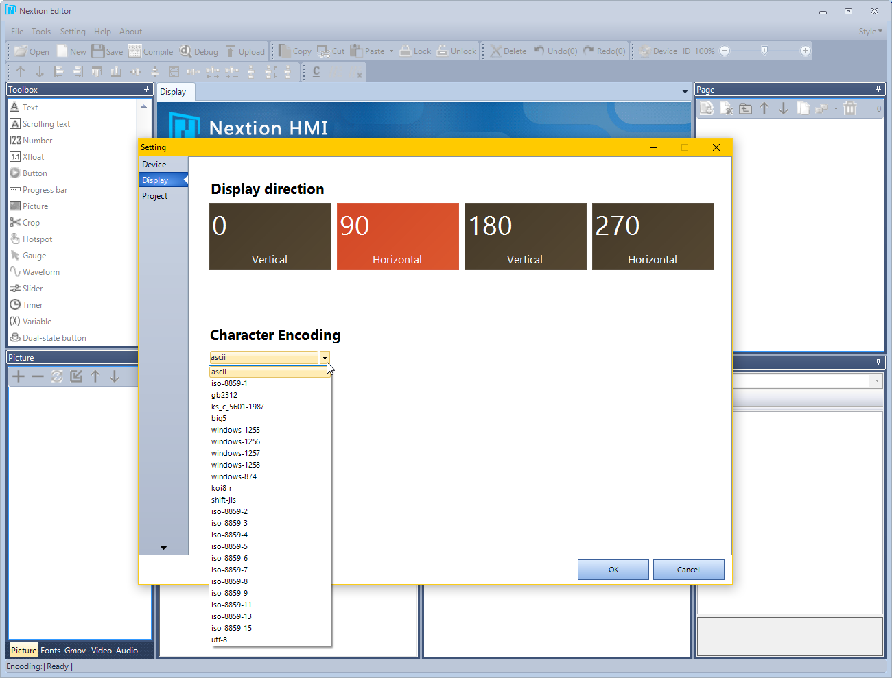
And another option that we have to choose is Character Encoding, which has a lot of options and also has utf-8 , that in theory it can support Thai language as well, plus Windows-874 (TIS-620). which is a code page in Thai language to use as well (But probably won't work because Thai fonts are now all UTF-8) for this time, we haven't used it yet. So we will choose ascii first, then press OK to start creating the screen.
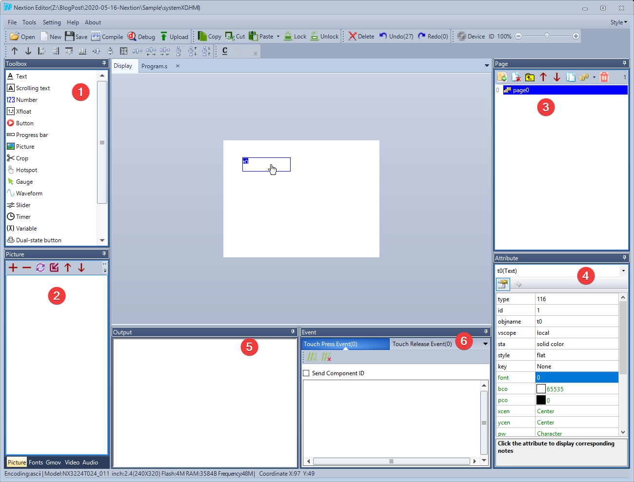
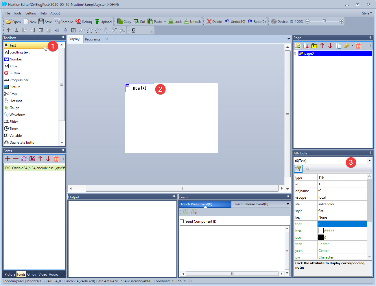
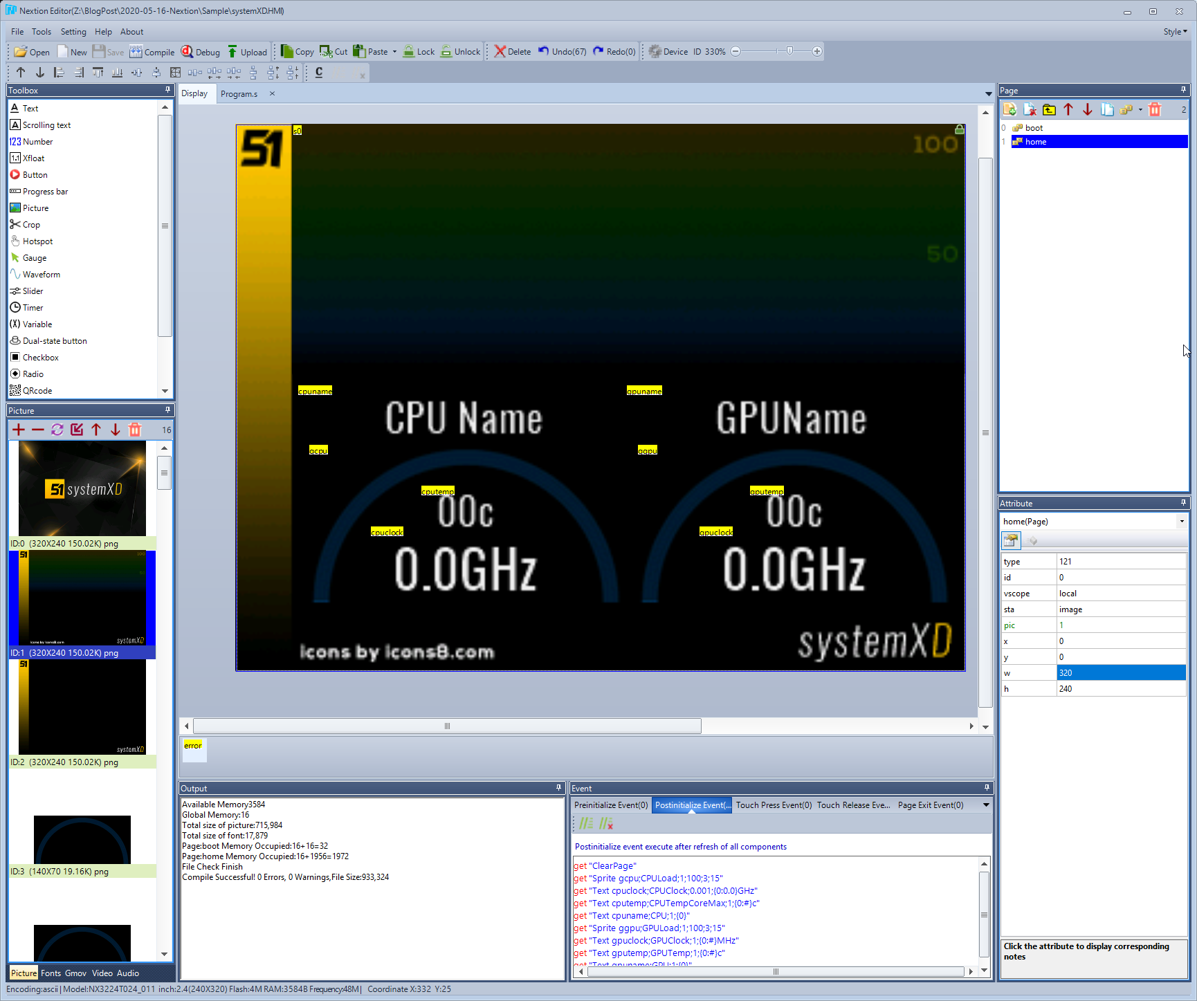
The Nextion Editor program looks very similar to Visual Basic / Visual Studio. On the left side (1) is a Toolbox, which has a selection of screen parts (Control) that we can use with Resource (2). used in our project On the right will be Page (3) or different screens in our project. Of course, we can make our project have multiple pages. Attribute (4) defines the properties of each screen element, and below is Output (5) where various warning messages are displayed. From the program and Event (6) is the part that we will use to write code to respond or order various tasks. with our screen
start screen design
The first step before we can do anything We'll need to create a font first, the Nextion Editor has its tools, it's in the Tools menu and then the Font Generator.
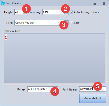
In this screen we have to choose the height of the characters. From our trial run, on our 2.4" screen, the smallest size that's comfortable to read is about 20-24. The process of creating a font is to set the size first (1) if you want to use multiple font sizes, you'll need to The band pressed again. Then choose Encoding (2) to match our project, which is ascii, and choose the font you like (3) . If you sell it, don't forget to check the license of the font first. (If it's a standard Windows font, they don't use it for publishing. You should look for free fonts from the web. http://dafont.com to use) and to not make the file size too large We can subset (4), select only ASCII characters, i.e. only 255 original standard characters, and finally, make sure to give the font a descriptive name (5).so that we are not confused about which font it is what size exactly So I named it Oswald24.
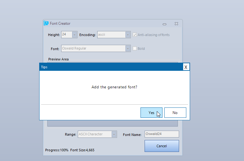
When you press Generate Font, it will be a .zi file, you can answer Yes to put it into your project.
After that, at the Toolbox, try to press (1) Text to bring out the Control Text, we will get a blue box with the word newtxt (2) and the Attribute screen will change a bit. Displays the settings of the currently selected Control Text (3) .
(If someone secretly skips the process of Generate Font when putting Text, it will be an empty white box. no characters)
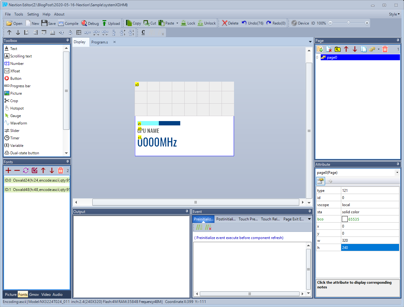
Alright, now let's take a Control Progress Bar and another Text with a larger font size (by adding more Generate Fonts) and Waveform, and adjust the color to look like this.
Oh, don't forget that it has buttons to arrange the Control.

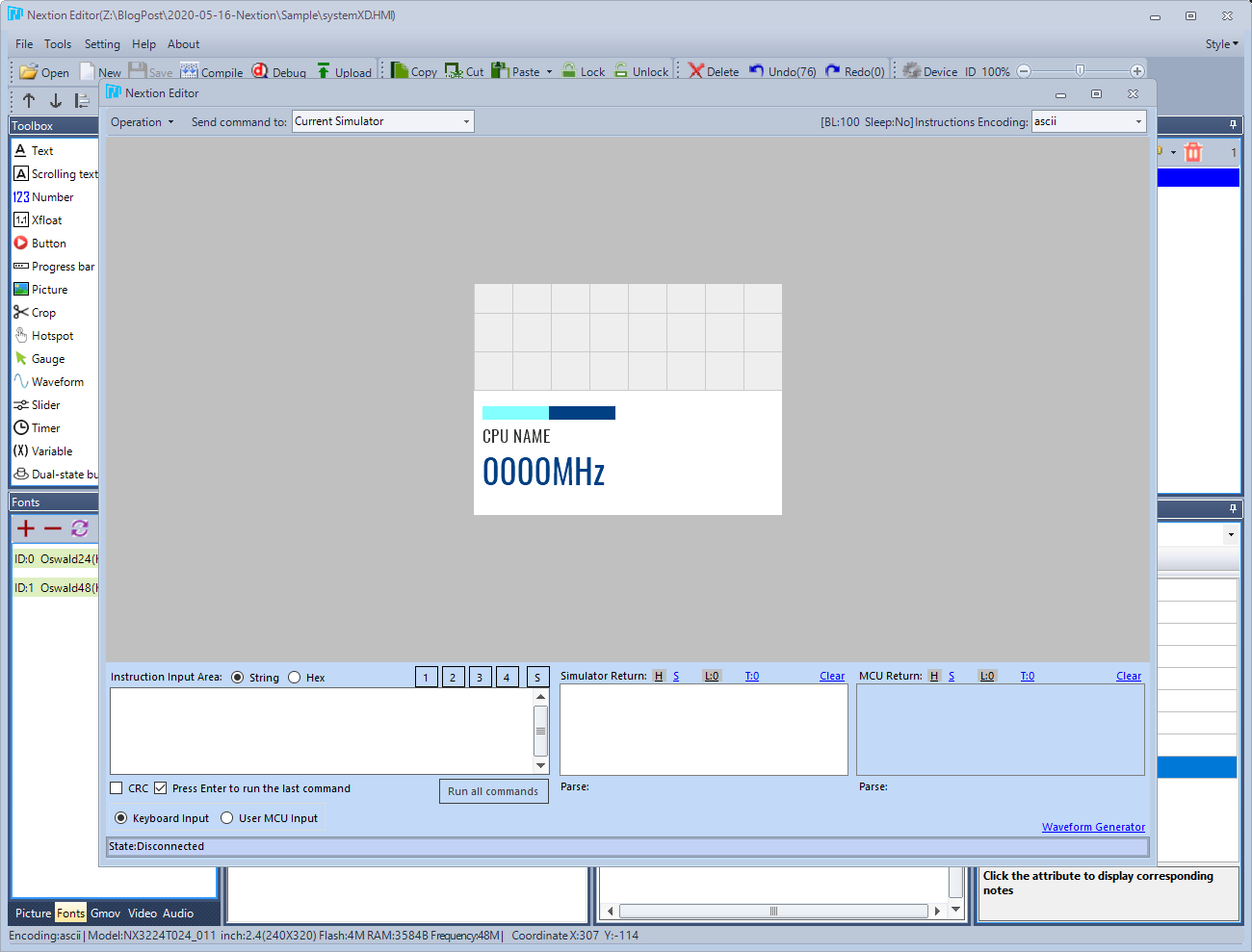
Done. What are you waiting for? We press Debug to try it out. Click on the button that says Debug in the Toolbar under the menu. This will open the Simulator. Note that it's a Simulator. Being a Simulator means that it doesn't exactly match the real hardware like an Emulator. You should try it on a real screen as well.
Nextion work orders
The working principle of Nextion is that the Nextion is a device that takes care of all display matters. (Presentation Layer or View) . The MCU is responsible for sending commands to the Nextion to modify the display. In other words, MCU is a Controller/Model or Business Layer .
In order to operate Nextion, we have to send commands in Nextion language like Script language. The commands that Nextion understand will be listed on this page. https://nextion.tech/instruction-set You can go and read it first.
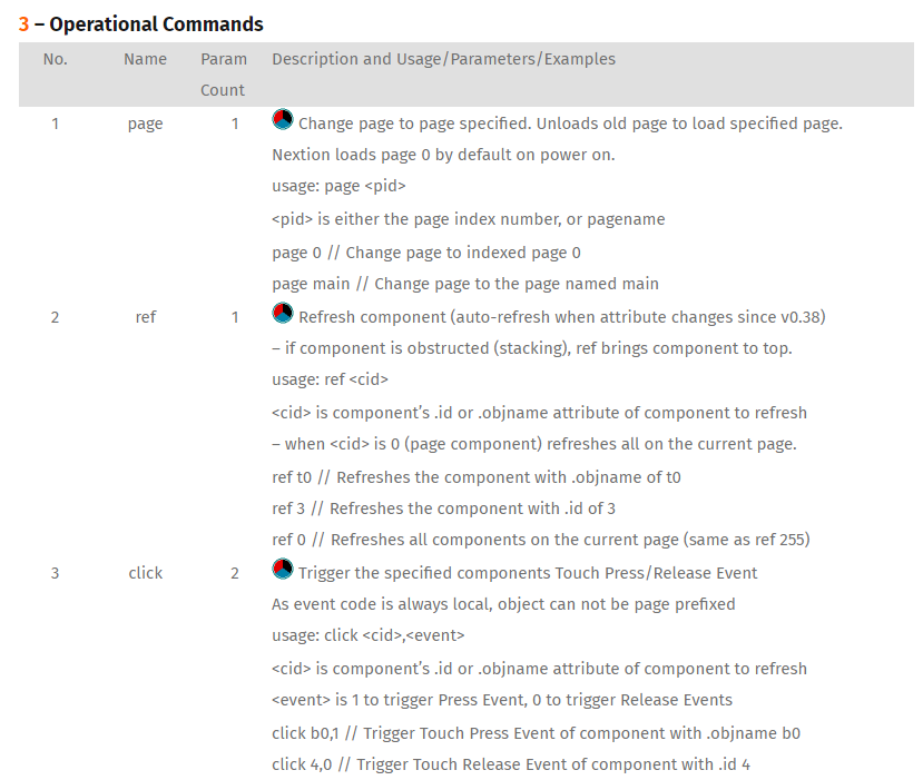
But the basic principle that must be understood is
- Nextion's controls are like variables. The variable has an attribute inside it that we can set (set) or read out (get).
- Nextion language does not have an Expression Tree , it is only one instruction, for example, you cannot use t0.txt=t1.txt+t2.txt like this, only need to do it step by step. is to be separated into t0.txt+=t1.txt and t0.txt+=t2.txt like this
- Nextion has no decimal calculations at all. All calculations are whole integers. If it happens that you already know that if you divide it, you get an arithmetic number. It takes multiplication 10, 100, 1000 to help.
So if we want to change the text of the first Text that we put down, which the Nextion Editor will automatically name as t0, we will have to send the command as
t0.txt= "hello world"
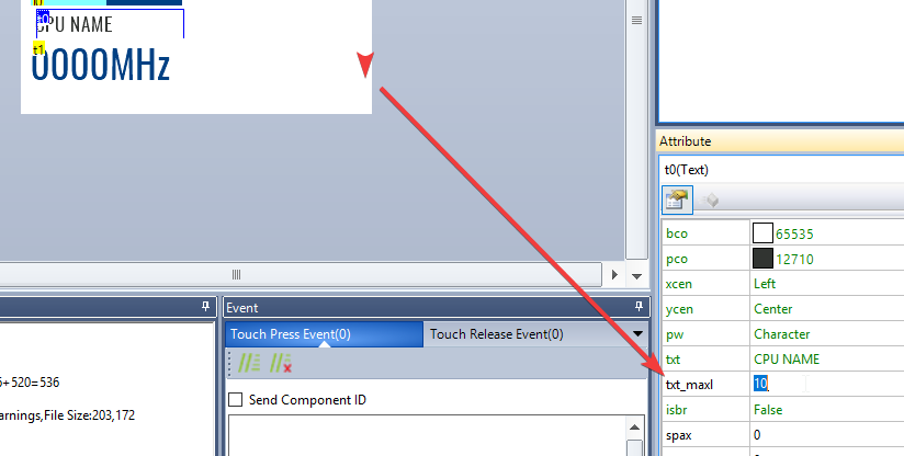
When we press Enter, we will see that the text in the t0 field has changed from "CPU NAME" when we initially set it to hello worl ...eh, why is there a missing d ? Because Text, usually when creating new, will reserve space in memory for only 10 characters, Hello world has 11 characters (including spaces), so it is missing 1 character, which we can add. can By changing the value of txt_maxl when designing the screen.
And if we change the value of Progress Bar to show only 10% left? It's easy, just use j0.val=10 .
Using Waveforms
For Waveform, it's a line graph display. will use a different method than usual is to use this command To pass one point in a Waveform
add [ waveform id code ],[ waveform channel up to 4 channels ],[ numbers 0-255 ]
order details
- The waveform's id can be seen from the Attribute screen of the screen I just made here. Chance will be number 4 and Control's id can be changed. If the screen is rearranged, then if the screen is modified You have to check this number again.
- Waveform's channel is that in the displayed graph There can be a maximum of 4 lines. Which number do we pass the value to? The number of channels can be set with Attribute ch .
- The number 0-255 is the Y value of the point that will be sent, where 255 is the top, 0 is the bottom, but it is a bit complicated because the Waveform will not scale the value at all, for example, if the graph we have Height is 255 Pixel and dis is set to 100 (100% or 1x). If point 255 is sent, point 255 will be exactly at the top of the graph. But if our graph is only 115, sending point 255 to Waveform will make this point Break through the graph because the waveform with a height of 115 Pixel can only put a value of 115
in order to make our point not penetrate the graph. We will also need to configure the Waveform's dis Attribute.where it is the percentage height of the graph. Compared to 255, for example, if our waveform has a height of 115, we would need to put dis at 45 (45% or 0.45 times), which is from 115 divided 255 times 100. The point 255 will be at the top of the chart at height 115. Pixel is almost perfect. That's almost right. Because the calculation will be all integers.
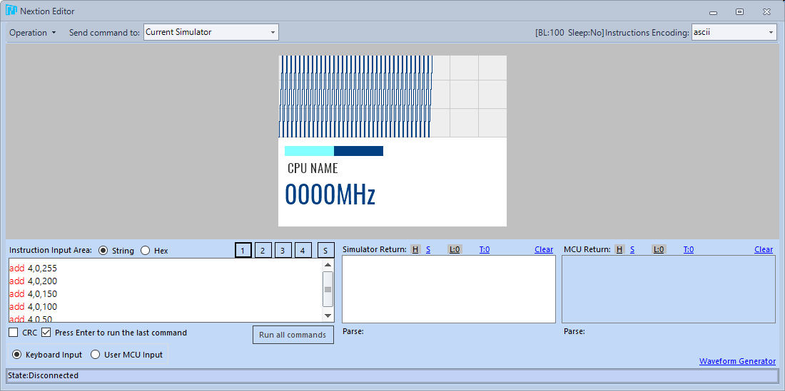
Suppose we try to enter the following command: (Don't forget to change 4 to waveform id on your own screen too)
add 4,0,255
add 4,0,200
add 4,0,150
add 4,0,100
add 4,0,50
add 4,0,0
Then press Run all commands repeatedly, you will get a zigzag graph like this.
Adding a background image and making the background blur effect.
for adding a background image We have to add images to our project's Resource first , similar to when making a mobile app these days by pressing the + button on the Picture screen (bottom left corner) and selecting an image file. It can be used immediately by the original file. It can be any file, but it is recommended that it should be a PNG image because it will get the same image as the original we made with the image editing program. The Nextion Editor will convert the image to a format that works with the screen as quickly as possible. automatic and colors are automatically reduced to 16-bit (65,536 colors)
Almost all Controls have an attribute called sta , which can choose between solid color, crop image, and image (full image, which forces the Control to be the same size as the background image).
What's interesting is the crop image, because with this attribute, you can trick the control's background into clear by selecting a background image. It is the same image as the Page background image (click on an empty background of the screen to modify the Attribute of the Page) , the Control will pull the image of the background only in the same position as the Control placed itself. But it doesn't really make the Control background clear. That is, if stacked It will cover itself well behind. (It will be the same as the screen design on Windows in the past.)
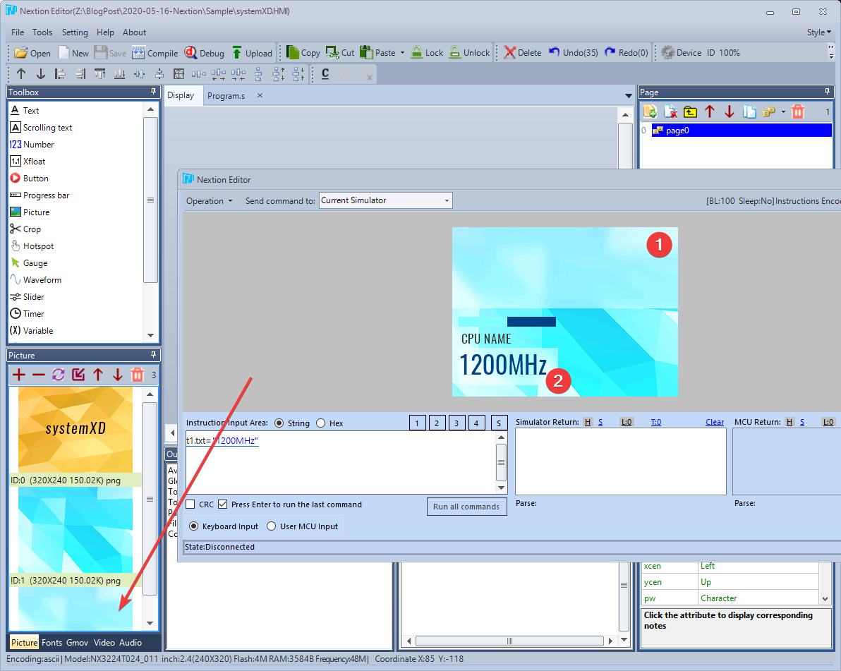
In addition, we can use this ability to make the background blur effect as well By inserting the same image as the background image but with blur effect (pointing arrow) then choose Attribute sta as the crop image but choose the image (Attribute pic ) as the blur instead. From the picture, it will be that the points (1) and (2) are images from another image that is blurry. but in the exact same position
Making a project with multiple pages
For use with MCU, often have to send commands from Nextion back to tell the MCU as well to make an appointment, for example, the screen is already open. What screen are you on now? what about this which is the best point to send these commands It must be when the screen finishes loading.
It's the same with SystemX. Moreover, SystemX programs and the Nextion screen often start differently. So one possible way is for Nextion to have a Boot screen first, then when SystemX is connected to Nextion, SystemX tells Nextion to change to Home screen which sends data back to SystemX again. as we have designed
for adding a new page You can do this by pressing the Add button in the Page screen in the top right corner only. And we can change the name of the page by right clicking. for easy memorization and reference later And we can also sort the pages. The first page (the 0) is typically the first screen that starts when Nextion opens.
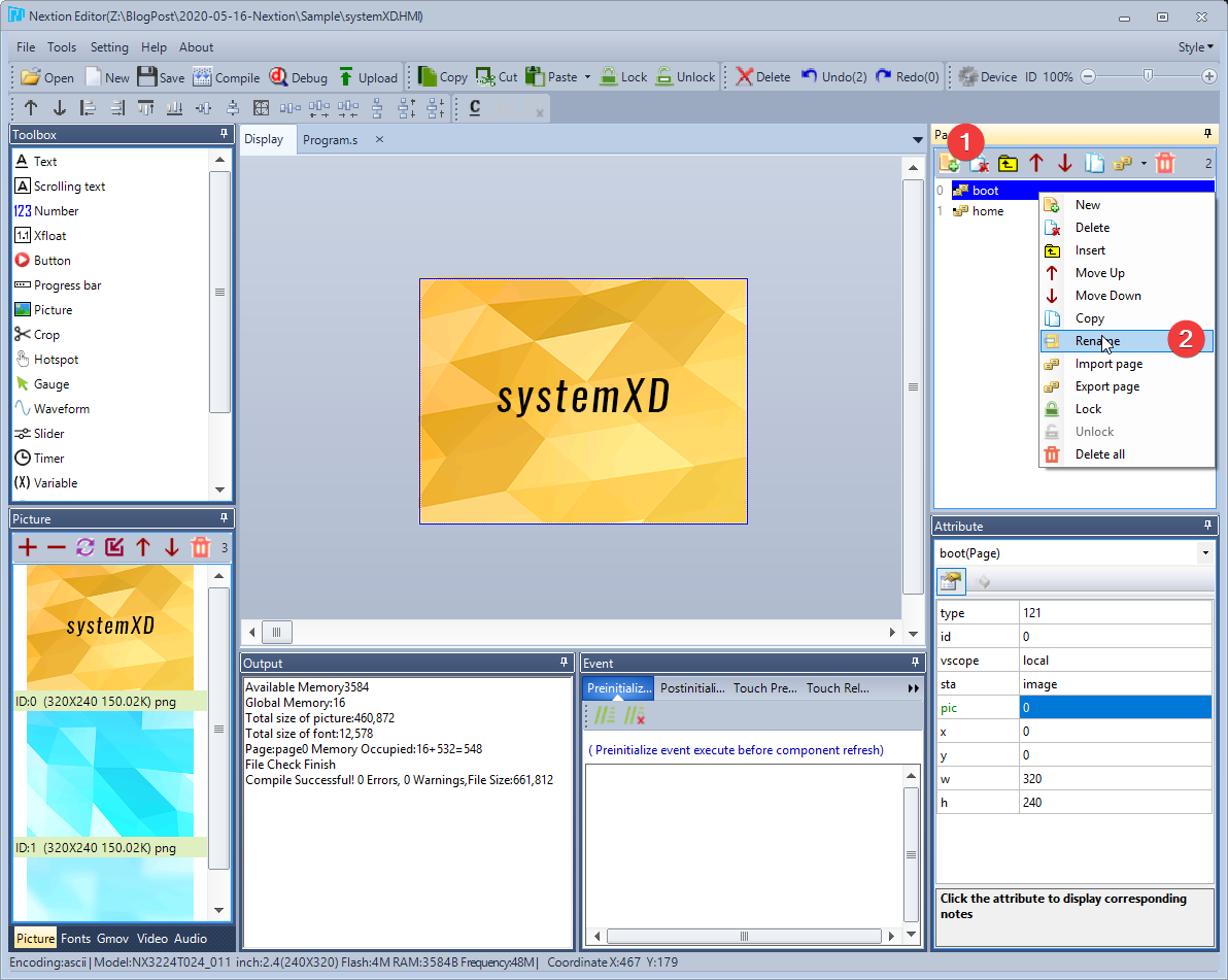
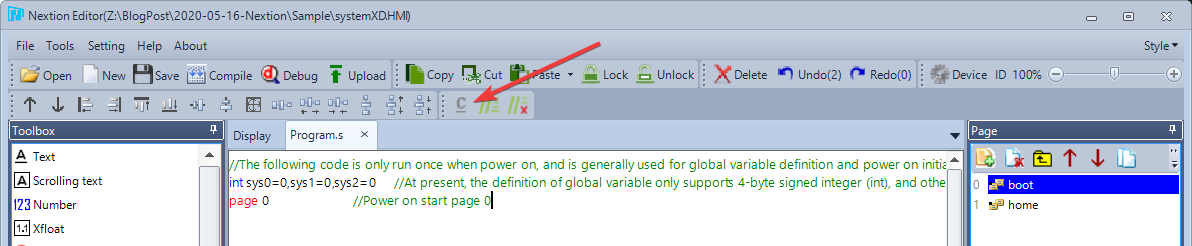
(But if you really don't want page 0 to be the first page It can be edited by pressing the C button on the Toolbar. This will open the code to start Nextion.)
As for the use with SystemX , there must be a boot screen and a home screen. The boot screen is the open screen while SystemX has not contacted. When SystemX has contacted Nextion, it will send a command to change the screen. It's the home page.
page change method
We can use the command Into the event (Event) of various Control if you try to press on the empty area. will select a Page which will have the following events
- PreInitialize - The code that runs (Run) before the screen starts drawing the Control.
- PostInitialize - Code that runs after Control is displayed on Page and ready to wait for commands. It is an Event suitable for sending to SystemX or MCU that the screen is ready to receive commands.
- Touch Press - when your finger is pressed against the screen. But still not released, if it is a button, it will be when the button image collapses. This Event is suitable for use in the event that the button has to be pressed and held in order to achieve the function, such as pressing the volume up-down.
- Touch Release - When a finger is pressed against the screen Lifted off the screen, if it's a button, it's when the button image. bounce back up This event is suitable for sending commands such as opening a door, etc.
- PageExit - The code that runs at this screen. about to be closed Suitable for clearing data on the MCU side.
And each control can have a different event. According to its usage, such as Timer, which is a Control that sends Events periodically for us to write code that refreshes the screen, there will be no Event PageExit in it, etc.
For example, if you want when touching the screen from the boot screen and then switch the page to the home screen, we would have to put a command in the Event Touch Release :
home page
During typing, there will always be an Auto Complete guide. Guarantee that there is no mistake, of course, when trying to debug, you will find that we can change the page from the boot page to the home page by clicking (tapping) on the screen.
Sending data back to SystemX / MCU
How to send data back to SystemX via Serial Port can be done by using the command
get "data to send"
In order to send data to send via Serial Port, or if you want to remove value from Control, you can use Control name and desired Attribute such as
get t0.txt
Then it's at the SystemX or MCU how to interpret what is sent. We will have to write a program from the MCU side to understand our own transmission. In conclusion, we have to design our own protocol (Protocol) to send and receive data as well (or use the Nextion SDK for Arduino).
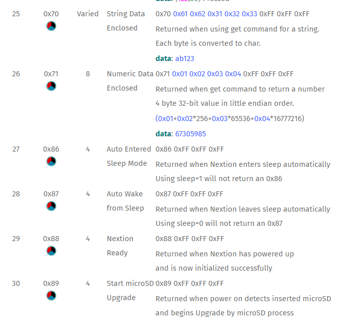
The format of the data returned will be in accordance with the document stated herein https://nextion.tech/instruction-set/#s7 that is, it will be the letter p (0x70) followed by the sent message and Byte 255 lined up 3 bytes if it is text data. So we may simplify our protocol. By providing information from Nextion, all can be sent in letters as well.
In the case of SystemX , what SystemX needs from Nextion is which Control to display what information? Or simply called "Data Binding", it sounds complicated, but it actually teaches SystemX how to send commands to Nextion when new data from the Sensor comes in. It will send Nextion's commands through Serial Port back as Nextion specified from the sent commands.
There are five simple commands supported by SystemX: (For Deduplicate, further descriptions are given below, and the names of valid sensors are in the appendix).
- ClearPage : This clears all bindings, meaning that SystemX will not send any commands to Nextion again and clears any previously remembered by SystemX. It should be the first command every time you enter a new screen. The command format that must be written on the Nextion side is
get "ClearPage"
- Value [ Control Name ];[ Sensor Id ];[ Value Factor ] ;[Deduplicate] instructs SystemX to pass a value from a specified sensor to a control that has an attribute val (eg Progress Bar) , providing a value read from the sensor. Multiply by Factor number first. For example, if you want Progress Bar j0 to display the value from Sensor CPU Load, you can use the command:
get "Value j0;CPULoad;1;false"
- Text [ Control Name ];[ Sensor Id ];[ Value Factor ];[ Format ] ;[Deduplicate] instructs SystemX to pass a value from a specified Sensor to a Control that has an Attribute txt (eg Text) where Format can be defined. Yes, according to C# String Format (full details here
https://docs.microsoft.com/en-us/dotnet/standard/base-types/standard-numeric-format-strings ) .
For example, if you want to display the CPU speed in t1, which will be numbered in MHz and we will have the word MHz at the end as well, you will have to use the command that
get "Text t1;CPUClock;1;{0:#,#}MHz;false"
Note that {0:#,#} is a Format String for having , separating numbers into thousands. and omit the decimal and have MHz at the end
If you want to display the CPU speed in t1 in GHz, which we have to divide by 1000 first (which is multiplied by 0.001) , we must use the command:
get "Text t1;CPUClock;0.001;{0:0.0}GHz;false"
Note that {0:0.0} is a Format String forcing 1 decimal place, and forcing a leading 0 if it is less than 0.
And if you want to display the CPU name in t0 only, you will have to write the command
get "Text t0;CPU;0.001;{0};false"
Note that {0} means no format is applied, the CPU is text-valued, factoring has no effect on the data.
- Graph [ Control Id ];[ Channel ];[ Sensor Id ];[ Value Factor ];[ Y Max ];[ X Repeat ] : This instructs SystemX to pass the sensor values to the specified channel to the Waveform by setting values. The maximum of the graph is a given Y Max value, for example, if you want Show a graph of the hottest Core temperature on the CPU in Channel 0 of Waveform Id number 4, at the top of the graph means the temperature is 90c and repeat the same value 5 times, then use the command that
get "Graph 4;0;CPUTempCoreMax;1;90;5"
The resulting 5 is from the fact that we define a 320 Pixel width graph and want users to If you can see the graph going back about 1 minute
, then you have to send the original value 5 times (320 divided by 60 = 5.33).
Do not forget that Nextion will not scale the value for you. Don't forget to set the waveform dis when designing.
- Sprite [ Control Name ];[ Sensor Id ];[ Value Factor ];[ Max Value ];[ Start Picture Index ];[ End Picture Index ] ;[Deduplicate] : Changes the image of a Control with an Attribute pic (eg Picture Box ) by using images in sequence, the closer the value of the Sensor is to the value of the Max value, it will use the next sequence of images, for example, if there are sprites from images number 3 to 15 and the value of Sensor is 96 from Max The 100 images that will be displayed in the control will be the image number 15, etc.
get "Sprite p0;CPULoad;1;100;3;15;false"
Wondering what the Sprite looks like? It's a series of pictures like this. (But usually he will save them together in one image) From this example, there are 13 images. If we set the Max value to 100 and the current Sensor value is 50, SystemX will send it to tell Nextion that the controller will use it. 6th picture, etc. (or 7)

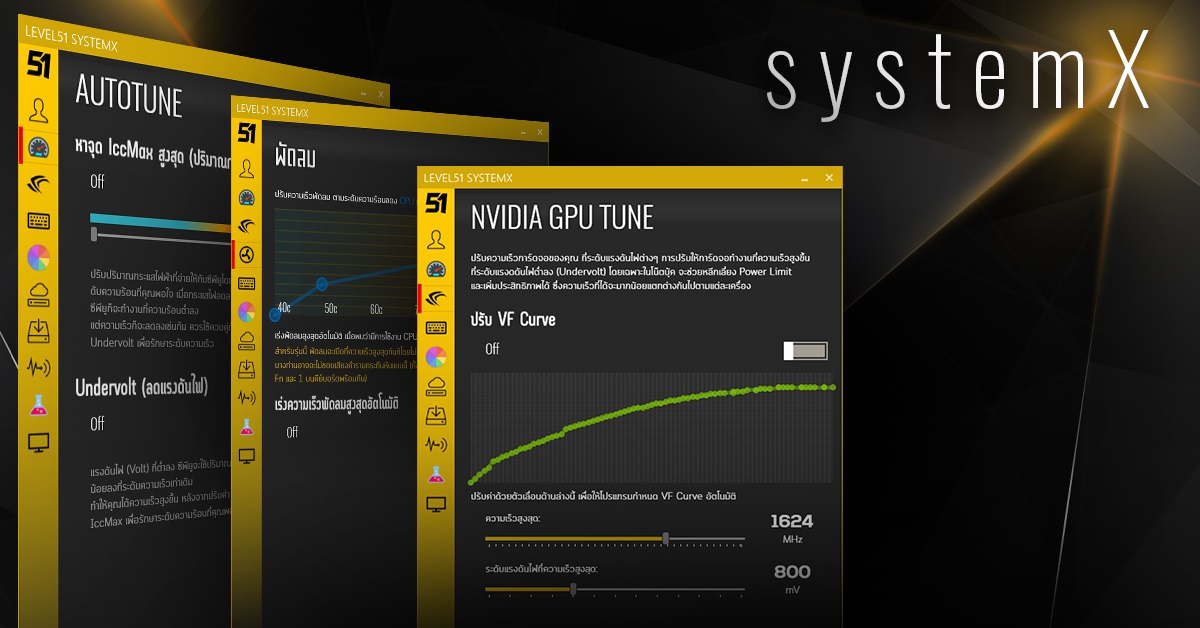
Now I've designed more screens to have both CPU/GPU and use Sprite to make a semicircular donut like the SystemX screen on my computer. come out like this You can try to follow.
and the code to make the screen It can be used as follows (insert in Event Postinitialize of Page)
get "ClearPage"
get "Sprite gcpu;CPULoad;1;100;3;15;true"
get "Text cpuclock;CPUClock;0.001;{0:0.0}GHz;false"
get "Text cputemp;CPUTempCoreMax;1;{0 :#}c;false"
get "Text cpuname;CPU;1;{0};true"
get "Sprite ggpu;GPULoad;1;100;3;15;true"
get "Text gpuclock;GPUClock;1;{0 :#}MHz;false"
get "Text gputemp;GPUTemp;1;{0:#}c;false"
get "Text gpuname;GPU;1;{0};true"
get "Graph 2;0;CPUTempCoreMax;1 ;100;5;"
get "Graph 2;1;GPUTemp;1;100;5"
flickering screen fix (only happens in the real Nextion)
Notice that I have grouped And sort the order of Sprite before Text as well, and some order Deduplicate to True. This technical term is called Draw Queue (Paint Queue, Paint Order) because Nextion does not do Buffering . Sending orders to Nextion. This will cause the display to change immediately, and the controls are out of order. If we draw Text before Sprite, which in Design, Sprite is after Text will make the text disappear. because the image from Sprite that I drew later was superimposed on it.
and even though we are in good order It can still cause flashing images as well. This is caused by the overlapping of Controls and sending commands immediately affects the screen. So we'll see for a moment the Control placed in the front disappears as the Control behind it has been updated, which will draw over the front Control before the front Control will draw again.
SystemX's Deduplicate option will try to help here. by not sending the same command over and over to reduce the screen update rate This will reduce some symptoms of the screen flickering and SystemX also has to send commands com_stop, com_star (wrong writing) to allow all commands to be in the Nextion first, and then process it in one go. to shorten the blinking further. But the right way is to be careful not to overlap the controls.
How to test with SystemX
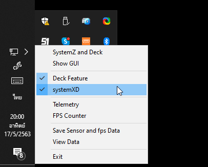
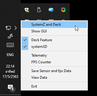
After SystemX is opened, right-click and select the systemXD option to enable integration with Nextion.
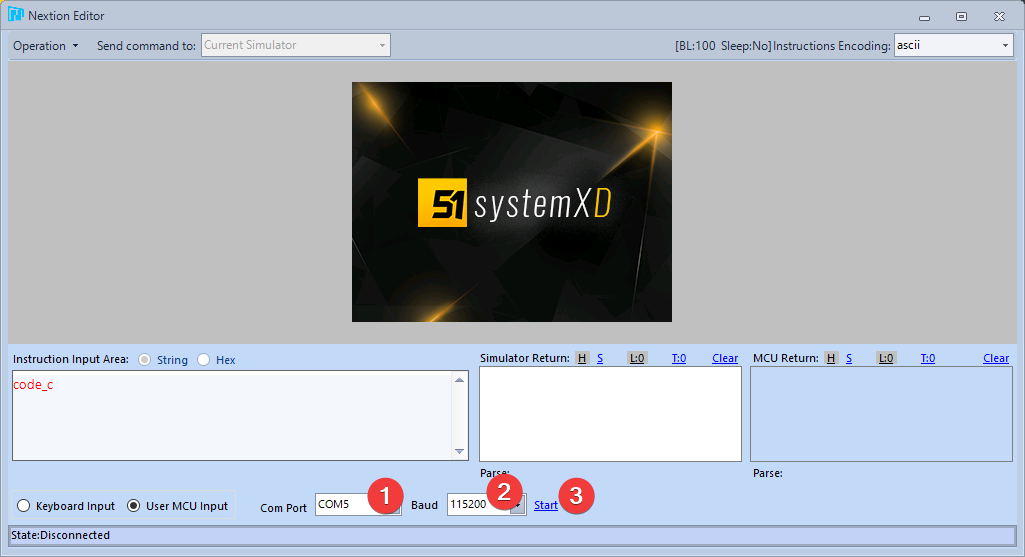
While there is a checkmark in front of systemXD, SystemX looks for a com0com or CH340 comport to connect to it. Then let us come back to the Nextion Editor screen and press Debug. Then we can command the Simulator to connect to the COM Port to talk to SystemX by selecting the User MCU Input and selecting the COM Port that is com0com (1) from Then set the Baud Rate to 921600 (2 wrong pictures) and then press Start (3) . If that happens, Access Denied means SystemX is using that Port. Change to another counterpart.
After getting the connected COM Port There may be another problem that SystemX has been connected to com0com for a long time, causing a lot of data stuck in the simulation COM Port until Nextion can't process it. The solution is to stop systemXD first and then open the Simulator to allow the Simulator to fetch the data. come all Then press to open again.
If all fixes are successful We can see that on the Simulator Return side is a command that Nextion sends to SystemX (which is the letter p followed by the command we defined. and closed with 255 3 bytes (contiguous). On the side of MCU Return, it is an instruction that SystemX sends to Nextion, which is a command to set the Text value, or enter the value into the Waveform in the same way that we type it ourselves.
final left is to test with the real thing!
Upgrading to Nextion
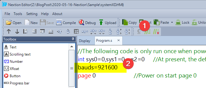
When we are ready to send the ROM to work on our Nextion screen, the last step is Come in to change the Startup code to change the Baud Rate from normal 9600 to 921600 first because SystemX will order to open COM Port at this speed only.
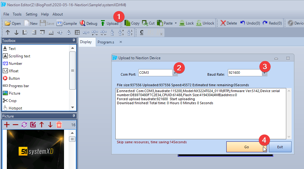
Then press the upload button and select COM Port, Baud Rate as well, the Nextion Editor will build the ROM into a .TFT file and send it to Nextion for us, ready to order Restart the Nextion as well, ready to use immediately.
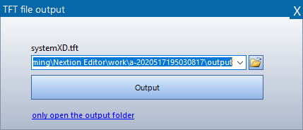
As for if we want to share this file for other people to use as well. You can create a .TFT file from the menu File -> TFT File Output, then select a folder and press Output. For this .TFT file, if you want to send it to Nextion, you need to copy it into a MicroSD and plug it into Nextion before. Plug in the cable, when Nextion detects the MicroSD it will automatically update itself.
end
hope this post Might be able to give a guide for those who are interested in playing with this Nextion screen and have tried to make it a screen that actually works. thought it would be easy to do And get the concept of Nextion, purely , more complete than trying to connect with Arduino itself, which has to sit and write code on Arduino again, and if you haven't tried it yet Will load a sample file of systemXD and try to move around. You can take some and if that happens It has been made into a skin. can then be sent into the system
SUBMIT SKINS TO SYSTEMX GALLERY
DOWNLOAD SYSTEMXD PROJECT FILE
Note: Nextion has an SDK for Arduino available, but their SDK design attempts to make Nextion a GUI library , which is one possible approach. But it will cause the overall project structure design to be somewhat distorted. is the code to display/response to the user/State screen operation It will be mixed in the Arduino as well instead of Nextion to manage all of them. Then summed up to order Arduino to do anything, and Arduino was stuck at the time of editing the code, waiting for a very long time when burning down the ROM before it could run. This kind of development made it even more slow.
Ready screen We also have one for sale~
As for if you If you are interested in getting a screen like this to use, don't forget that you can chat with us (or http://m.me/level51pc ) to order now. The set includes a USB cable, a screen, and a complete frame with stand. (Frame/Stand are 3D Print out)
Addendum: So where did the name Sensor come from?
Our SystemX program can be viewed through a mobile phone, called SystemZ. You can click to open it by right-clicking on the 51 icon and selecting SystemZ and Deck, or open a browser to http://localhost:5293/systemz/index. .html itself.
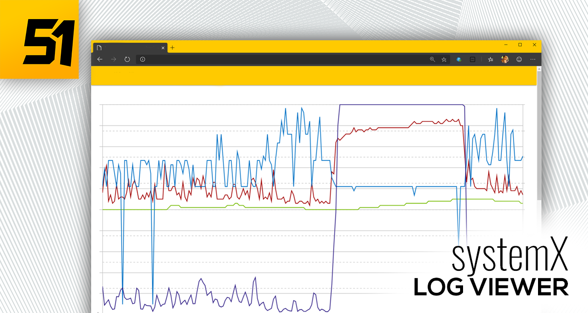
In case anyone doesn't know, our SystemX can view via mobile, collect data from Sensor and create a graph.
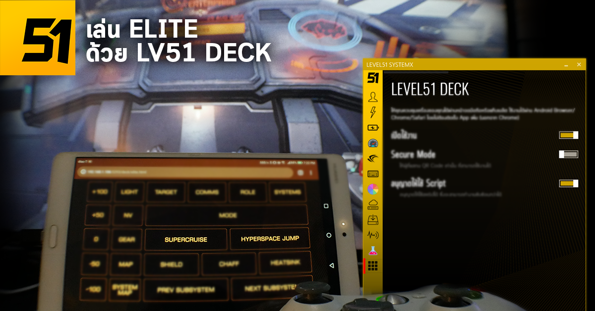
and can also use a mobile phone Simulate keyboard key presses. (You can use your mobile phone to play games) too~
In this screen, there will be a list of sensors in the device. exactly written /intelcpu/0/clock/1 like this is the Sensor Id.
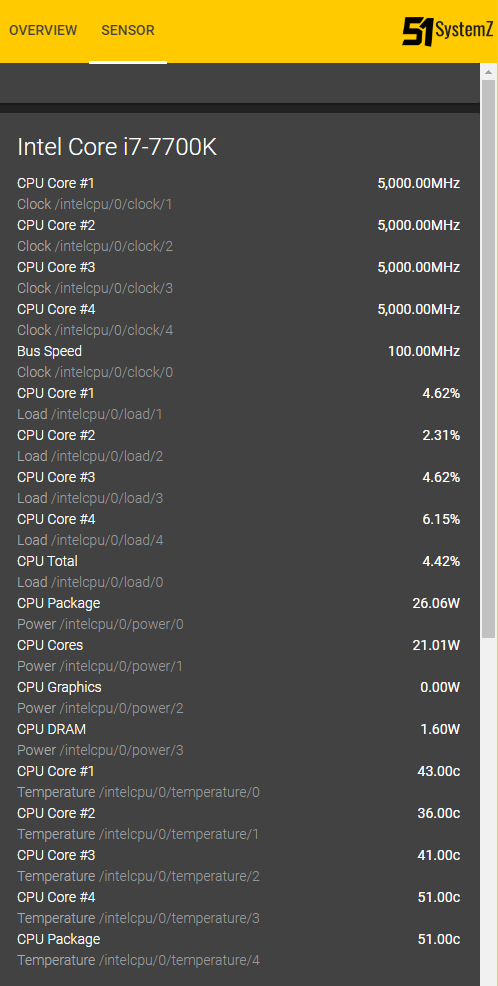
and in addition, there will be a special Sensor Id as follows that can be called to be used, which will be a Sensor that summarizes the values from other Sensors again
- CPU : CPU name eg i7-7700K
- GPU : GPU name, for example RTX2060.
- CPUTempAverage : Average core temperature in degrees Celsius.
- CPUTempCoreMax : Hottest Core temperature in degrees Celsius.
- CPUClock : Average speed of all cores in MHz.
- CPULoad : % CPU usage
- GPUTemp : GPU Core temperature in degrees Celsius.
- GPULoad : % GPU usage
- GPUClock : GPU Core speed in MHz.
There is also a sensor that can read the value from SystemX's FPS Counter to be read out as well. You have to open SystemX's FPS Counter first before the value will be displayed. Otherwise it will be null (Empty String).
- FrameTime : The amount of time between frames of the game or program that uses DirectX that is currently the top screen.
- FPS : is 1000 / FrameTime is the Frame Per Second value that we are familiar with.
- CurrentProcess : The name of the game or program that uses DirectX that is currently the top screen.